Scanning laser projector
Preface (or, Why?)
In the meantime while I gather enough courage/dedication to finish the projects I have started (e.g. master's degree, carpc build), I wanted to share what else I have been working on.
It all started with an idea about SLS 3d printer, using light-curing resin and DLP projector. I do have a projector, but I was very reluctant to use it for 3d printing, as I find that quite wasteful.
One day, Max, a member of our local hackerspace told me an idea he had, on creating machine which could ease the pain of fabbing PCB's at home. Basically, the machine uses UV laser and a rotating mirror assembly to reflect laser beam against photoresist board. Turn laser on/off at the right moments and a line is drawn. Move the laser head, "draw" the next line, profit.
I got so interested in this idea for two reasons:
- Because I experienced frustrating pain trying to get good AND repeatable results when fabbing PCBs using conventional methods (print traces on transparent, lay it over PCB and use UV lightbox to expose uncovered PCB)
- I saw use for technology like this in a 3d printer, by replacing projector with laser head mounted on a moving axis.
What?
I use UV laser diode with optics module, which I got at ebay. Diode's emission spectrum peaks at 405nm, it's optical rating is 700mW. It comes from a BluRay disk drive. Sometimes I wonder, how can a part be sold cheaper when it's extracted from replacement part (BluRay drive sleds), than ordered from usual electronic parts retailers.
Anyway, laser diodes require constant current power supply. Sam's Laser FAQ contains a lot of really useful information on this. I built a driver based on a similar project, by members of German hackerspace.
By this time, I could light a cigarette from the laser beam, good job.
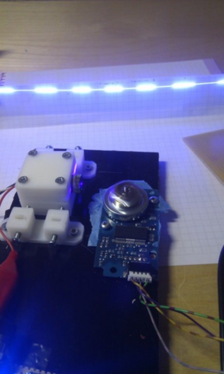
Next, I got a laserhead from used/dead HP LaserJet printer. Tearing it apart, I discovered a motor driver, AN8247SB for which I was not able find any useful documentation. However I found someone who has reverse-engineered the connections to this driver, and using this information, I got a spinning mirror in no time.
Okay, we got a laser beam and a spinning mirror. At this point, I had a nice blue line drawn on paper. Next, I needed some way of detecting when laser beam is at "home" position. There are several ways how to do it- either by using tacho output from laser driver (which I seemingly fried by connecting to ground), or using an opto-interrupter to "see" when mirror/motor shaft is at some position, or, alternatively, use some means to detect laser beam itself.
I opted for the latter one. I could not find any phototransistors rated for 405nm but I found out that you can use an ordinary LED as light detector. As with all electronic parts, there are several ways to do this- either by exploting the fact that diode works similar to capacitor, and measure the time taken for this "capacitor" to discharge, or by connecting LED in reverse and measuring the voltage generated across leads. Amplification and some filtering is required though, as voltage we're dealing with is quite small. The first way seemed too slow for me, so, once again, I opted the latter way.
Code
At this point I needed some way to send pulses to laser driver based on information from laser "home" position sensor. From some back-of-the napkin calculations I found that I would need to drive the laser driver at approximately 500kHz to 1MHz frequency to achieve a resolution of 0.1mm (at 200mm long line segment, laser mounted 100mm apart of the line, and 3000RPM). At this point I only had experience with Atmel's AVR line of microcontrollers, but I had two TI's Stellaris Launchpads. Since I wanted to play around with ARM MCU's, I went with Stellaris.
Laser driver input is hooked to SPI/SSI output on Stellaris, so I don't have to worry about exact timing of pulses- MCU's hardware handles that for me, I just have to calculate SPI frequency, and start transfer when the laser beam hits "home".
Mechanical design
At this point I could draw a line I wanted with laser. However, the laser needs to be moved along, perpendicular to the drawn line.
After a bit of fiddling with CAD software, this is what I came up with:

 It uses some pieces of plywood, some RepRap'ped mounts for linear rods, LM8UUL
linear bearings from Far East, regular, M8-sized, threaded rod, and a stepper from
my reserves.
It uses some pieces of plywood, some RepRap'ped mounts for linear rods, LM8UUL
linear bearings from Far East, regular, M8-sized, threaded rod, and a stepper from
my reserves.
Friction between the nut and threaded rod is a problem at this time. I will probably try to make a nut from POM/Acetal plastics, as it should result in less friction. Ideally, one would use either trapezoidal threaded rods (ACME threaded rod), or maybe even belt&pulley drive.
Current status
Wrapping up mechanical build, preparing for testing the laser on photoresist PCBs.
Current code, schematics, and mechanical design CAD files can be found in this project's page on Github.
TBD: finish firmware for MCU, write control software on PC.
Comments