RaspberryPi powered car-pc
Why?
Some time ago, I got myself a Raspberry Pi. Initially it was supposed to replace my home-theater PC but I found it's too slow. So, I had a problem- what to do with such a nitty device of Pi.
This was not the only problem I had- my old Volvo has built in navigation system, with motorised LCD and neat keys on steering wheel. The problem, you may ask? Volvo stopped doing new maps for it 5 years ago. Heck, just use the old maps! You see, I live in Latvia and as you could have guessed- there are no maps available in the country I live in.

What?
I am currently building a navigation system to replace original navigation system. As a bonus feature, I'd like to hook into car's audio system- the original head-unit only has CD and casette trays and no aux input. Since noone burns CD's these days I am aiming to use Raspberry Pi for audio as well.
The display itself is a 6.5" TFT LCD screen with (admittedly, quite low) resolution of 400x234. My thinking goes- if it's good enough for factory navigation, it will be good enough for me.
Overview of car hardware
The parts of car this project integrates in are:
-
LCD display
As mentioned earlier it's a 6.5" low-res TFT screen. It has composite and RGB inputs for video, and pseudo-serial communication link. One must send data via this communcation port to switch on display, switch between RGB (default) to composite video input. Display brightness can also be controlled via this serial link. Since Raspberry Pi only has HDMI and composite video outputs, the display needs to be switched to composite input.
-
Steering wheel controls
There are 6 buttons on steering wheel for control of navigation system- Back, Enter and 4 directional keys (up/down/left/right). Luckily the button state is sent as messages on CAN bus, which I can easily hook into without re-wiring.
-
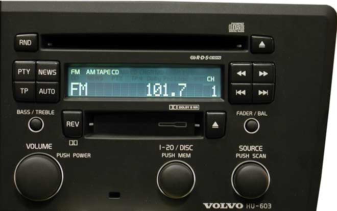
Head-unit (HU)
In-car audio comes from this. My HU has CD and casette readers alas no auxiliary input (at least, I can't find one in pinout). The only way to integrate with HU from my carpc is by pretending to be a CD/MD changer. This brings us to MELBUS- a proprietary protocol developed by Mitsubishi for Volvo. There is absolutely no official documentation on how it works (except having CLK/BUSY/DATA pins and left/right/voice guide audio signals), but there are some projects on the internet which have successfully emulated CD-changer of these head-units, so I'm going to do the same.
-
Control module in trunk
The original navigation control module is located in trunk, and is connected to CAN bus, LCD screen and HU via MELBUS port. It's basically useless for me as there are no maps available for my country.
How?
My plan is to replace the control module in trunk completely. It's basically a controller which interfaces low-level hardware (CANbus, MELBUS) and RaspberryPi (via serial port).
Controller I'm using is an Atmega 328p. For CAN bus communication I'm using fairly common combination of Microchip's MCP2551 & MCP2515. Together they let me interface CAN bus via SPI bus, which Atmega 328p has hardware support. Thanks goes to Steven, about his excellent writeup on using CAN bus for Arduino
With MELBUS, it's a little bit trickier. There are three signal lines: CLOCK/DATA/BUSY. From what I've gathered so far, controller has to pull down BUSY line on startup to indicate there's a device connected, and then send out identification data on clock pulses. Clock is 100kHz provided by head-unit. The software for this part is not implemented yet but there are some examples on the internet.
It's dead-simple to implement a communication between RPi and Atmega- just use the UART with a level convertor.
Since Raspberry Pi runs from 5V, I'm using off-the-Farnell PCB-mountable switching DC-DC convertor. It's rated for 5A which actually is too much, and I may re-purpose it for more demanding tasks later.
RaspberryPi will have GPS receiver, 3G modem and flash drive attached through powered USB hub. The estimated power draw of these devices is up to 1A@5V. That's 5W of power, or 0.42A@12V car's battery power. This would drain a fully charged 70Ah battery in a week, and I don't want it. So, I have to figure out a way to power down Raspberry Pi when engine is killed. I am aware that SSR/mosfets could be used but since I'm an electronics novice, it seems to be safer for me to use a relay for this.
And now, on to the build itself:
Comments